HARK FORUM › Generating a Measurement-based Transfer Function for RASP-LC › Reply To: Generating a Measurement-based Transfer Function for RASP-LC
Thank you for taking an interest in hark.
1a) Do we have to run the sound from the TSP ourselves?
Although synchronized recording can be accomplished using RASP-LC, due to the lack of documentation on how to do it, we recommend using un-synchronized recording for this device. This means the TSP response must be played and recorded by hand.
If you have a digital amplifier unit, connect the 2.5 mm jack on the side of RASP-LC to the digital-in (digital coaxial input Terminal) of the digital amplifier, then connect the output of the amplifier to the speaker. In this case, the quality will be better than playing the TSP audio file from the PC.
1b) Files for each source have a different initial indent, how to deal with it?
Because the TSP response will be recorded using un-synchronized recording method, we highly recommend you use our new algorithm Mouth TSP. The initial indents will need to be trimmed off so that all the “sources” align. They do not have to match completely but, the more aligned they are the better.
2) How many pulses do you need to reproduce? 17 or 20?
If you were to use our old method of creating the Transfer Function, at least 16 TSP responses were recommended although using more than that was also okay. With the introduction of our new Mouth TSP algorithm, the amount of TSP response needed has drastically been reduced. A total of about 3-4 responses should be enough. If your current “sources” already contain either 17 or 20 TSP response recordings, they can be used as is.
3) What is the accuracy of the installation of the microphone array and sound source is required for correct operation? 0.02 m will do?
We recommend that the speaker be placed within a 1 meter radius from the microphone array. Please note that the speaker should face the microphone array leaving only a 2-degree margin of error.
4) What are the settings to use in the Harktool5_gui? Sync. Add Num, TSP Offset, TF Calculation Type (use mouth TSP responses or use TSP responses) if responses file as attachments.
Because the TSP response was recorded using un-synchronized method, please follow the steps portrayed in TAMAGO`s transfer function generation manual. As shown in Figure 31 in said manual, most of the values will be left to their default settings.
We recommend that you trim all your “sources” as close to 0 as possible. Use Mouth TSP Record’s Mouth TSP Start and Mouth TSP End by default is set to 16,484 and 32,768 respectively. It is important that the range in frequencies that the sound source is expected to be in is within this period. Since a TSP response contains all the frequencies, the transfer function will be able to detect all types of sources like an alarm clock or a click of a pen. Please note that Mouth TSP Head Margin should be set to 128.
5) What view should the TF have when displayed in harhtool5_gui? (for 8 circle placed microphones(radius 0.09m) and 12 circle placed sources (radius 1 m))
In the case of geometric calculation, in order to generate an impulse from the relative position of the sound source and the microphone, the coordinate information (position information) of the arrangement file of the microphone must be described as accurately as possible. On the other hand, in the case of TSP recording, since impulses are generated from the recorded TSP, the arrangement file of the microphone only needs to have the same number of microphones as the number of channels of the microphone array. Therefore, in the case of TSP recording, there is no problem even if your microphone array and microphone arrangement are different when plotting the microphone placement file.
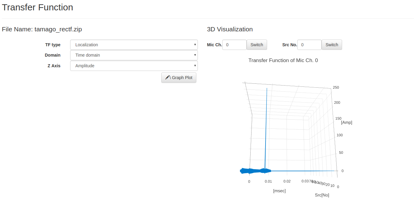
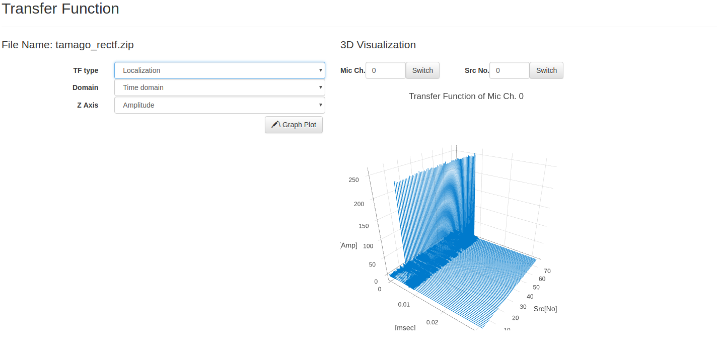
To check whether the Transfer Function was created correctly, please use HARKTOOL5’s visualize option selecting Localization, Time domain, and Amplitude accordingly and you should see a something resembling a waveform with an initial spike diminishing over time. Please see the attachments bellow.
To answer your original question, if you select a circle as the template in Create Sound Source Positions within HARKTOOL5, set to radius to 1 m, and used a 12 sound source layout file, a circular formation should be displayed.
-
This reply was modified 7 years, 7 months ago by
c.santiago.